High-Voltage Switchgear Temperature Measurement
High-Voltage Switchgear Temperature Measurement
Introduction: A running high-voltage switch cabinet, where the temperature of the internal contacts keeps rising, but it is difficult to accurately monitor due to the inability of the live parts to come into direct contact; or a large transformer, in a strong electromagnetic interference environment, the electronic temperature measurement equipment frequently gives false alarms…
These issues have long troubled power maintenance personnel. In environments with high voltage and strong electromagnetic interference, traditional temperature measurement techniques encounter numerous challenges:
Infrared temperature measurement: It can only measure the surface temperature and cannot directly measure live conductors.
Thermocouple: There is a problem with electromagnetic interference, and the insulation performance is difficult to guarantee.
Wireless temperature measurement: The signal is prone to interference and the battery life is limited.
Breakthrough in Fluorescent Fiber Optic Temperature Measurement Technology
The emergence of fluorescent optical fiber temperature measurement technology has provided a perfect solution to this problem. This technology makes use of the properties of fluorescent materials, using optical signals to achieve temperature perception, demodulation and transmission, truly realizing non-electrical detection and intrinsic safety.
1. Background
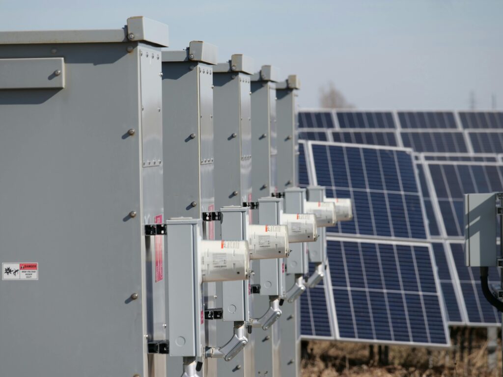
High‑voltage switchgear is a critical component in power transmission and distribution systems. Its reliability directly affects grid stability and operational safety. Overheating caused by poor contact, insulation degradation, load fluctuations, or environmental conditions is one of the most common failure modes in switchgear.
Fluorescent fiber optic temperature monitoring provides real‑time, high‑accuracy, and EMI‑immune temperature measurement, making it ideal for monitoring busbars, cable terminations, isolators, circuit breakers, and other high‑voltage components.
2. System Working Principle
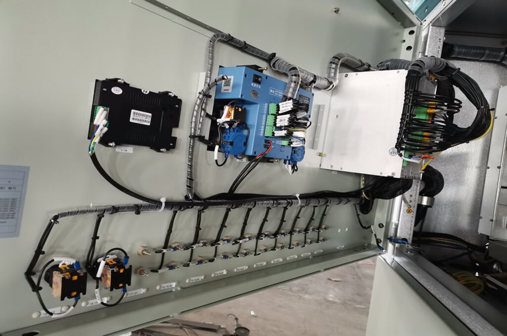
– Fluorescent fiber probes are installed at key hotspots inside the switchgear.
– The interrogator excites the fluorescent material and measures fluorescence decay time.
– Decay time is converted into precise temperature values.
– Data is transmitted to the SCADA or monitoring platform.
– Alarms and trend analysis support predictive maintenance.
Simplified System Architecture:
[Fluorescent Fiber Probes in Switchgear] → [Optical Interrogator / Temperature Host] → [Communication Network] → [Monitoring Platform / SCADA] → [Real‑Time Temperature • Alarms • Trends]
3. System Components
- Fluorescent Fiber Temperature Probes — Installed on busbars, cable joints, isolators, and breaker contacts.
- Optical Interrogator — Converts fluorescence decay time into temperature readings.
- Fiber‑Optic Cables — Provide passive, safe, EMI‑immune signal transmission.
- Communication Module — Supports RS485, Ethernet, IEC 61850, or wireless.
- Monitoring Platform — Displays real‑time temperature, alarms, and historical trends.
- Installation Accessories — Probe clamps, magnetic mounts, high‑voltage insulation sleeves.
4. Key Advantages
- Immune to electromagnetic interference (EMI)
- Safe for high‑voltage environments (passive optical sensing)
- Real‑time multi‑point temperature monitoring
- High accuracy and long‑term stability
- Supports predictive maintenance
- No electrical risk or grounding issues
- Suitable for GIS, AIS, RMU, and MV/HV switchgear
5. Performance Comparison Table
Parameter | Infrared Sensors | Fluorescent Fiber Optic Sensors |
EMI Immunity | Medium | Excellent |
Accuracy | Medium | High |
Real‑Time Monitoring | Limited | Full real‑time |
Installation in Enclosed Switchgear | Difficult | Fully supported |
Safety | Medium | Very High |
Maintenance | Frequent | Minimal |
6. Recommended Applications
- High‑voltage switchgear (AIS / GIS / MV / HV)
- Busbar temperature monitoring
- Cable termination and joint monitoring
- Circuit breaker contact temperature monitoring
- Ring main units (RMU)
- Smart substation and digital grid systems
7. Conclusion
Fluorescent fiber optic temperature monitoring provides a highly reliable, safe, and accurate solution for high‑voltage switchgear. Its immunity to electromagnetic interference and suitability for enclosed, high‑voltage environments make it essential for modern smart substations and predictive maintenance strategies.
JUST CLICK FOR BEST SOLUTION
Intelligent temperature and humidity control for both high and low temperatures, provider of power safety solutions