Instruction
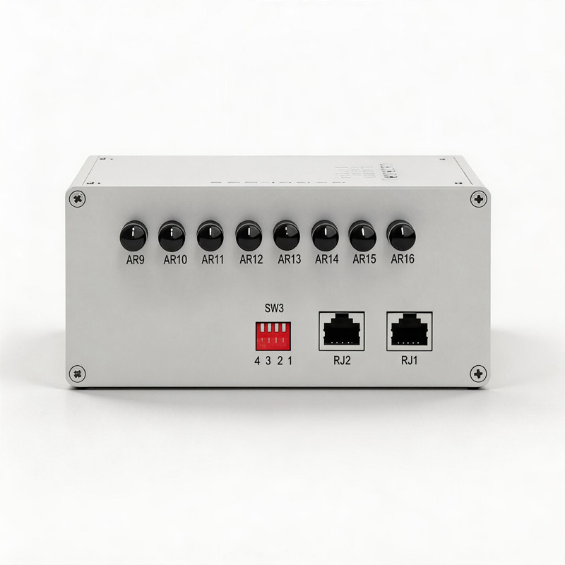
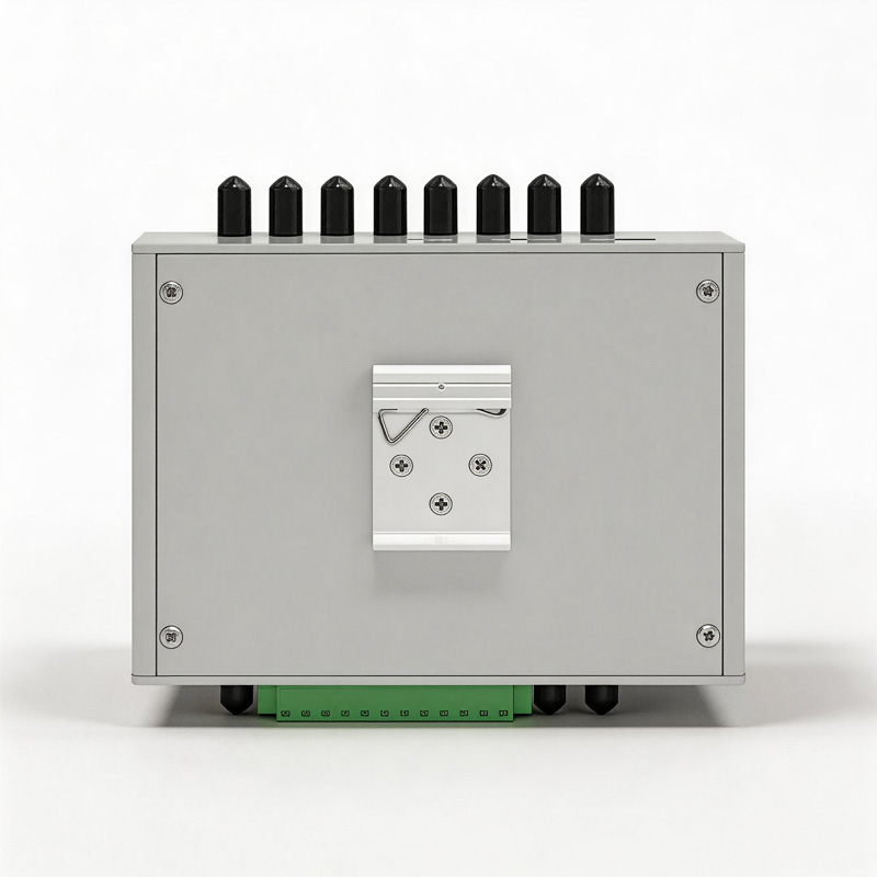
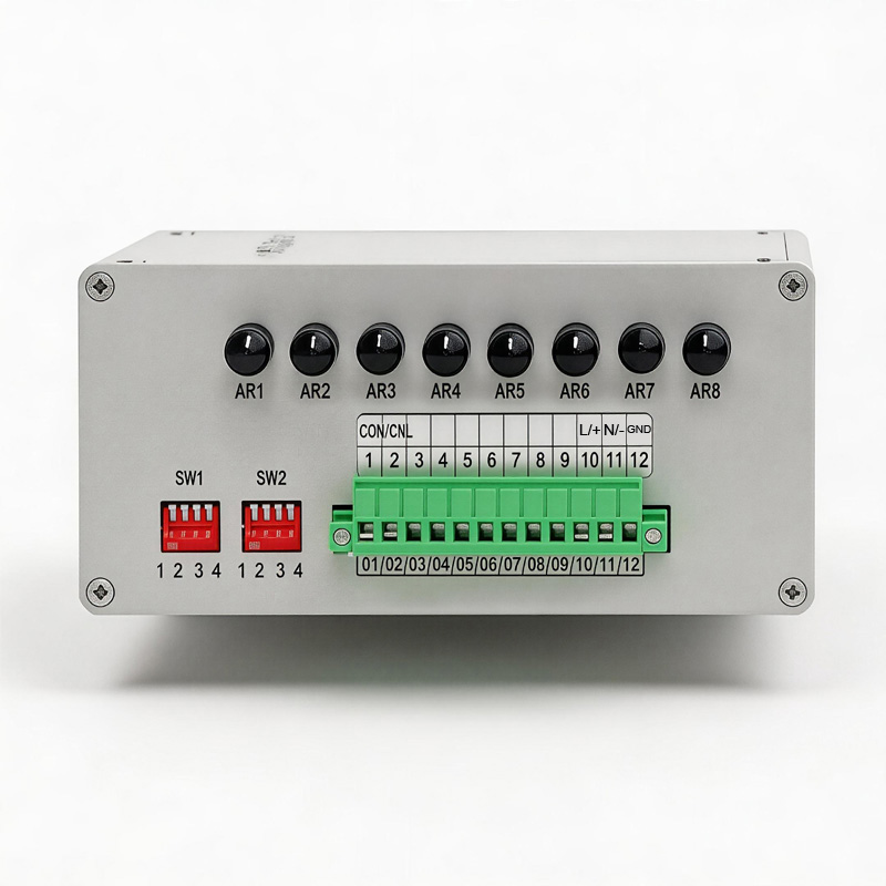
1. One side of the unit features 8 arc-detection interfaces, a 12-position Phoenix terminal block, and two DIP switches (SW1/SW2); the other side contains 8 additional arc-detection interfaces, two RJ45 ports (unused), and one DIP switch (SW3).
2. The expansion unit communicates with the main controller via a CAN bus. Pin 1 of the expansion unit’s 12-position Phoenix terminal serves as CANH and connects to Pin 9 of the main controller CPU module’s 10-position Phoenix terminal; Pin 2 of the expansion unit’s 12-position Phoenix terminal serves as CANL and connects to Pin 10 of the main controller CPU module’s 10-position Phoenix terminal.
3. Pins 10 and 11 of the expansion unit’s 12-position Phoenix terminal serve as the power supply interface, while Pin 12 serves as the EARTH ground connection. Pin 10 corresponds to L/+ and Pin 11 to N/-, supporting a 220V AC/DC power supply.
4. DIP switch SW1 is used to set the CAN communication address for this specific expansion module. For example, if only Bit 1 is switched down, the address is 1; if only Bit 2 is switched down, the address is 2; and if both Bit 1 and Bit 2 are switched down simultaneously, the address is 3.
5. For units shipped from the factory in pairs, the addresses are pre-configured as 1 and 2.
6. DIP switch SW2 controls the CAN bus termination resistor. When enabled (switched down)—as is the factory default setting—the resistor is active. If the main controller is connected to more than two expansion units, the termination resistor need only be enabled on a single expansion unit, depending on the specific site requirements.
7. The two RJ45 ports located on the opposite side of the unit are currently unused; DIP switch SW3 must therefore remain in the “off” (not switched down) position.
8. To utilize the expansion unit, simply complete the wiring as described in Step 2 and configure the address and termination resistor settings as described in Step 4; no further configuration is required on the main controller side. On the main controller’s LCD interface—specifically within the arc-detection measurement screen—the 17th displayed value represents the arc-detection reading from Expansion Unit 1 (address 1) in hexadecimal format. Subsequent values follow in sequential order according to their addresses (2, 3, 4, etc.), displaying the arc-detection readings transmitted by Expansion Units 2, 3, 4, and so on.
NOTICE:
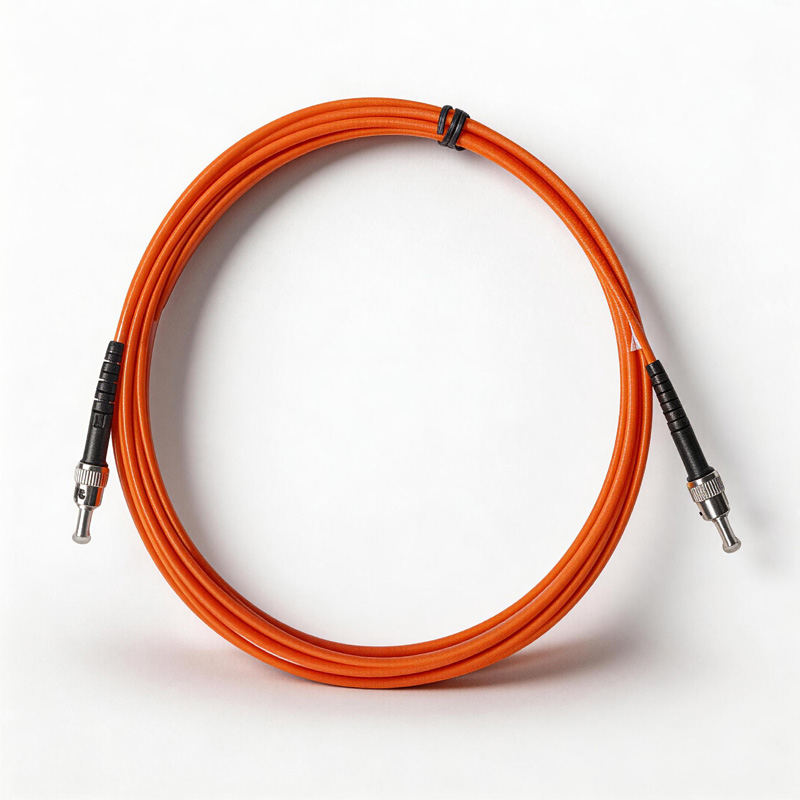
- Fiber optic cables must strictly not be bent at a small radius; during use, the bending radius shall not be less than 30 mm.
- Please avoid subjecting the equipment to severe shaking or impact during use and transport.
- During transport and storage, the ambient temperature must not fall below -40°C or exceed +50°C, and the surrounding environment must be free of corrosive gases. The original packaging box must be used during transport.
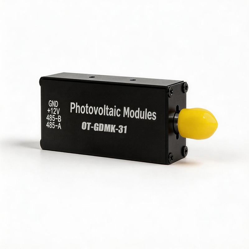
- Avoid contaminating or damaging the optoelectronic modules with oil stains or various chemical substances.