Features
(1) High Dielectric Strength
This is a fully optical measurement device. Within a creepage distance of 30 cm, the sensor can withstand power-frequency voltages exceeding 140 kV, thereby fully meeting the dielectric strength requirements for switchgear.
(2) Strong Resistance to Flashover Caused by Contamination
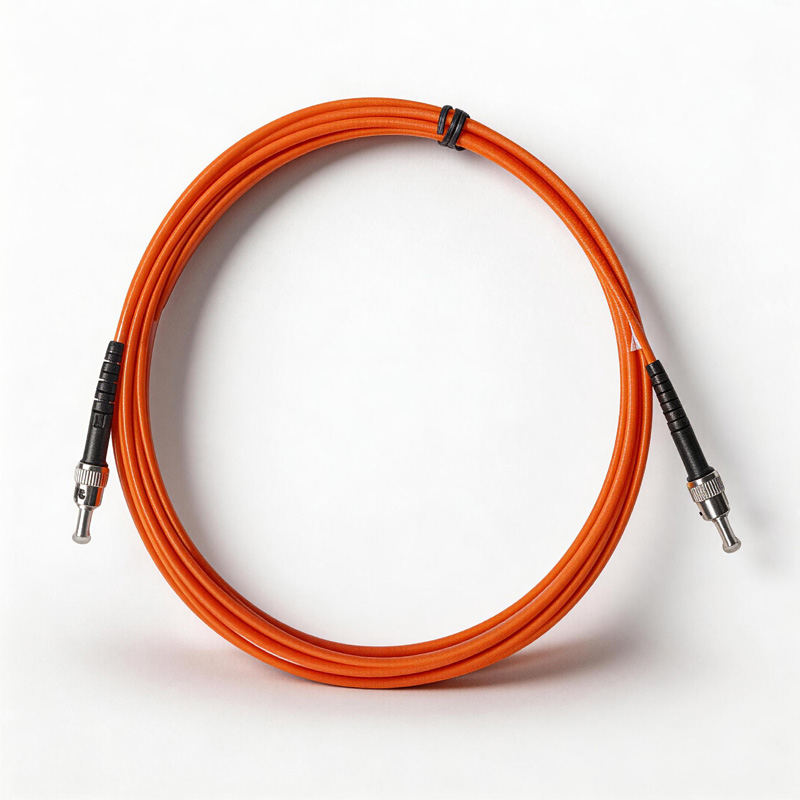
Tailored to different voltage levels, the fluorescent fiber-optic temperature measurement system employs special optical fibers—sheathed in either highly contamination-resistant silicone or PTFE—for signal transmission, thereby ensuring the overall safety of the system.
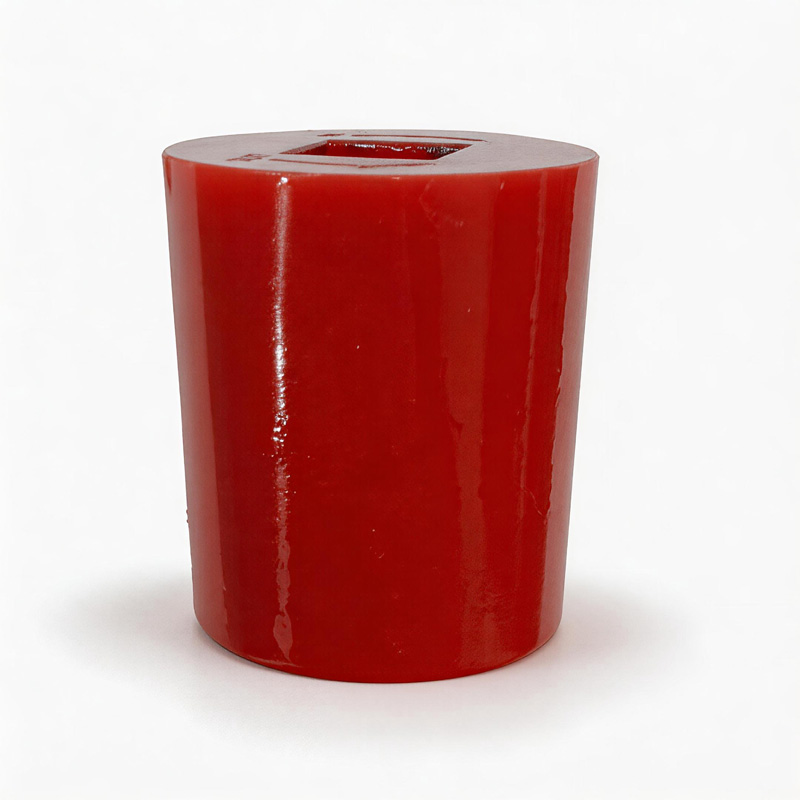
(3) High Reliability of Temperature-Sensing Materials
The temperature-sensing element within the sensor consists of a rare-earth material that is sensitive exclusively to temperature. The long-term stability of this material has been thoroughly validated, and related systems have been successfully deployed in equipment monitoring applications for over 30 years.
(4) Distributed System Architecture with High Stability
As a truly distributed system, it offers flexible configuration options. Each temperature measurement unit operates independently without mutual interference; consequently, a failure in a single component will not result in the failure of the entire system. This design ensures excellent robustness, reliability, and stability.
(5) Precise Positioning of Measurement Points
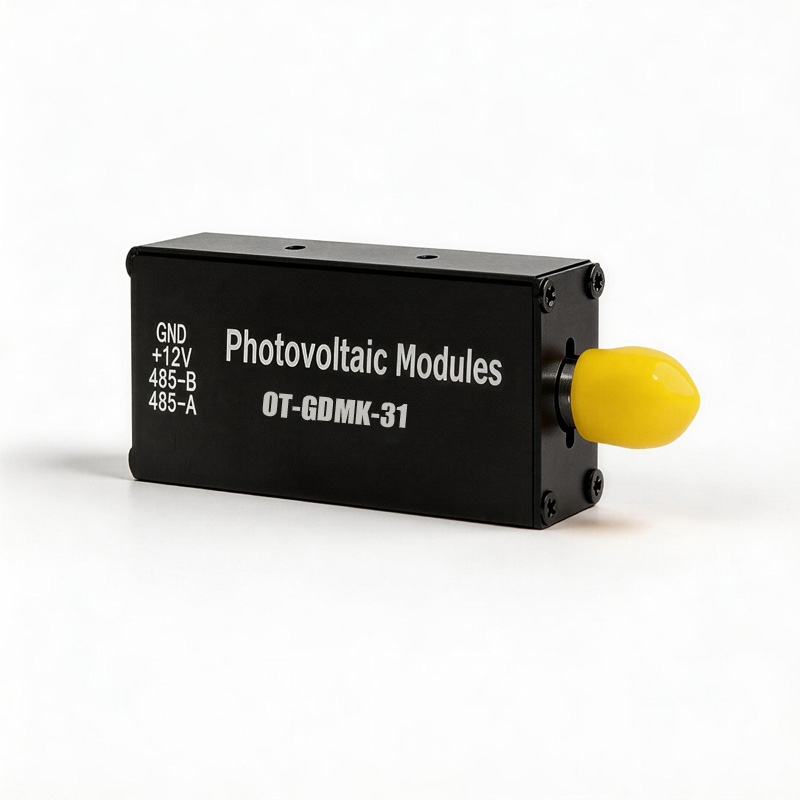
The temperature-sensing probe features a compact size (φ 2.3 mm), allowing for the precise positioning of the installation location.
(6) Short Measurement Cycle and High Real-Time Performance
The temperature measurement cycle for a single channel is approximately one second, thereby fully guaranteeing the timeliness of alarm notifications.
| Model |
OT-YGCW |
| Host Channels |
Customizable up to 48 Channels |
| Fiber Optic Temperature Transmitter Channels |
1–8 Channels (Customizable up to 24 Channels) |
| Measurement Range |
-40°C to +200°C (Customizable to 260°C, 360°C) |
| Operating Environment |
-20°C to +60°C |
| Storage Temperature |
-40°C to +70°C |
| Measurement Accuracy |
±0.5°C |
| Measurement Resolution |
0.1°C |
| Sampling Rate |
1 time/second |
| Host Power Supply |
AC 220V |
| Power Consumption |
<8W |
| Display |
LCD Display |
| Digital Outputs |
Default: 1-channel temperature alarm (Optional: Add 1 for dehumidification and 1 for cooling) |
| Communication Interface |
1-channel RS485 (Customizable to 2 channels) |
| Communication Protocol |
Standard Modbus-RTU Protocol |
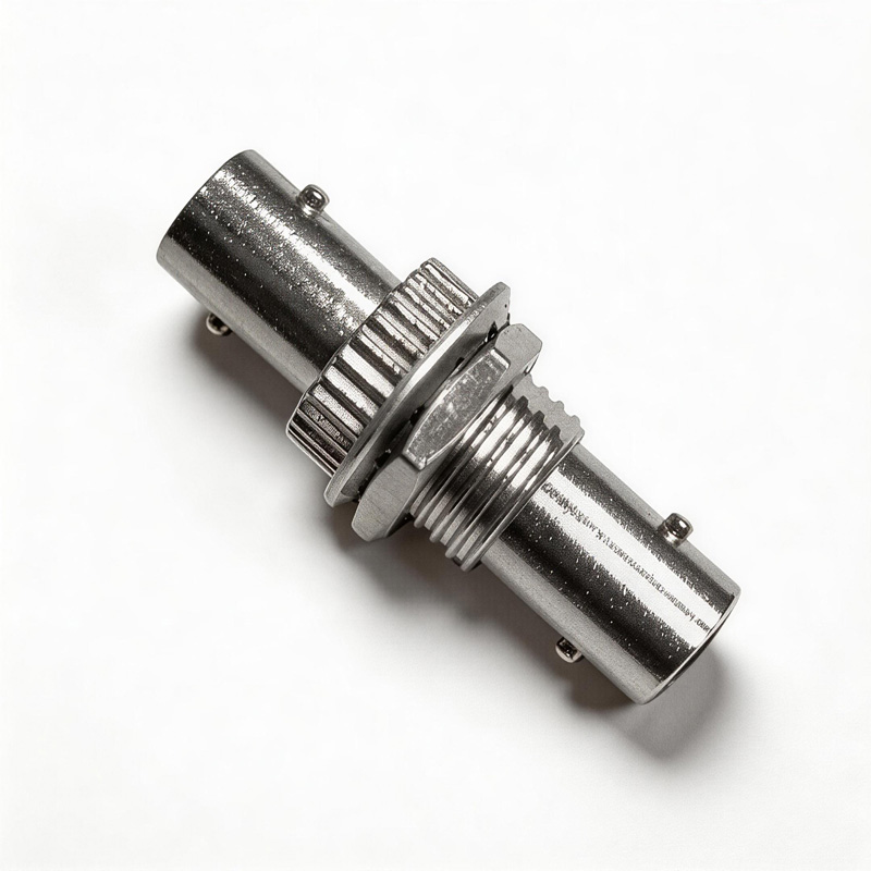
| Fiber Optic Connector |
Standard ST Connector |
| Probe Diameter |
Φ2.3 mm |
| Fiber Optic Sensor Length |
1 meter |
| Fiber Optic Extension Cable Length |
4 meters (Customizable length ≤ 10 meters) |
| Mounting Method |
Panel Mount |
| Dimensions (H × W × D) |
100 × 100 × 110 mm |
| Panel Cutout Dimensions (H × W) |
91 × 91 mm |